
FAQS
Top 10 Types of PV Accessories for Solar Projects?
A reliable solar project depends on more than panels, inverters, and batteries. PV Accessories connect, protect, support, and monitor the system throughout its service life. In the field, a poorly selected cable gland can admit water, while an undersized connector may create heat at a rooftop junction. Small components often carry serious responsibility. They influence installation speed, electrical safety, maintenance access, and long-term energy production.
This guide examines the top 10 types of PV Accessories used in residential, commercial, and utility-scale projects. It covers mounting rails, clamps, cable connectors, junction boxes, grounding products, combiner boxes, monitoring devices, and other practical components. Each category deserves attention from designers, installers, inspectors, and project owners. Product selection should match local weather, system voltage, conductor size, roof structure, and applicable electrical standards. Experience matters here. A component that works well in a dry warehouse may fail sooner beside saltwater or under repeated freeze-thaw cycles. Details matter.
No checklist is flawless. Unexpected site conditions can expose weak assumptions. A trusted supplier should provide clear datasheets, traceable certifications, installation instructions, and responsive technical support. Independent testing and professional inspection remain valuable, especially for high-voltage systems. The strongest projects treat accessories as engineered parts, not inexpensive afterthoughts. This article offers a practical framework for comparing their functions, risks, and applications before purchasing or installation begins.
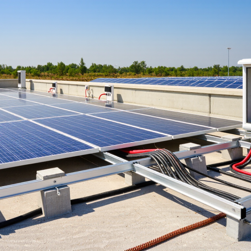
PV Accessories: Definition, Scope, and Role in Solar Projects
PV accessories are the supporting components that connect, protect, secure, and monitor photovoltaic equipment. They are not decorative additions. A well-designed solar project depends on their electrical, mechanical, and environmental performance.
The main categories include mounting structures, rails, clamps, DC cables, connectors, combiner boxes, fuses, DC isolators, surge protection devices, and monitoring equipment. Grounding and lightning protection also deserve careful attention. These parts manage current flow, reduce mechanical stress, limit fault damage, and help technicians inspect the system safely. In field reviews, loose connectors and poorly supported cables often create more trouble than the panels themselves. Small details matter.
Their scope changes with project size, roof type, climate, and operating voltage. Coastal sites may require stronger corrosion resistance. Snowy regions need higher structural load capacity. Monitoring devices can reveal abnormal voltage, temperature, or string performance before a failure spreads. However, accessory selection should follow verified specifications, installation instructions, and applicable electrical and construction requirements. A component that fits physically may still be electrically unsuitable. That mistake is easy to make. I also find that accessory lists are sometimes copied from older projects without checking current conditions. Engineers should review compatibility, protective coordination, cable routing, grounding continuity, and maintenance access before procurement. A clean drawing is useful, but it cannot replace an inspection under real sunlight, wind, dust, and heat.
Top 10 Types of PV Accessories for Solar Projects
PV accessories support electrical collection, circuit protection, installation, monitoring, grounding, and structural stability. The chart groups ten commonly used accessory types by their primary project role.
The classification includes DC cables, connectors, combiner boxes, fuses, disconnect switches, surge protection devices, monitoring devices, mounting rails, grounding components, and cable-management hardware.
Core Electrical Accessories for Power Collection and Distribution
Top 10 Types of PV Accessories for Solar Projects?
As solar capacity expands, reliable collection and distribution equipment becomes increasingly important. IRENA’s Renewable Capacity Statistics 2024 recorded about 346 GW of new solar capacity added worldwide in 2023. This scale increases pressure on every connection point. Core accessories include DC cables, connectors, string combiner boxes, DC fuses, DC isolators, and surge protection devices. Each component controls current, limits fault energy, or protects equipment from lightning and switching surges. Small details matter. A loose connector can create heat beneath an apparently healthy array.
On the AC side, projects commonly use AC distribution boards, circuit breakers, power transformers, and medium-voltage switchgear. Monitoring gateways complete the electrical chain by recording voltage, current, insulation status, and fault events. The IEA PVPS Trends 2024 report highlights the continuing growth of utility-scale PV, where long cable routes and higher operating voltages demand careful coordination between protection devices. Fuse ratings must match conductor capacity and short-circuit conditions. Isolation points should remain accessible during maintenance.
Field experience suggests that documentation is often weaker than the hardware. Labels fade. Cable routes change. A perfect design can still fail through poor torque control or incomplete testing. That is uncomfortable, but useful to remember. Commissioning should include polarity checks, insulation resistance testing, thermal inspection, and protection verification. These steps are not glamorous. They prevent expensive surprises.
Mounting and Structural Accessories for Panel Installation
Mounting accessories quietly determine whether a solar array survives real weather. The core parts include rails, roof hooks, racking brackets, mid-clamps, end-clamps, splice plates, ballast trays, and structural bolts. Grounding washers, cable clips, and protective caps also deserve attention. They prevent loose wiring and reduce corrosion around connection points.
Global solar capacity reached about 1,419 GW by the end of 2023, according to IRENA’s Renewable Capacity Statistics 2024. IEA PVPS reported more than 400 GW of new photovoltaic installations during the same year. This rapid expansion increases demand for reliable mounting systems, not merely cheaper components. Engineers should check roof loads, wind uplift, snow pressure, drainage paths, and thermal movement before selecting accessories. A clamp that fits the panel frame may still fail on a weak purlin.
Small details matter.
On a sloped roof, flashing must guide water away from penetrations. On a metal roof, rail alignment should follow the structural members, not visual convenience. For ground arrays, driven piles, concrete foundations, and adjustable brackets require different soil and load assessments.
Stainless steel or coated fasteners can limit galvanic corrosion, but material compatibility still needs verification. IRENA’s data confirms the market’s scale, yet installation quality remains uneven. In practice, rushed torque checks and missing washers are common weaknesses. A final inspection should record bolt torque, clamp position, bonding continuity, and drainage clearance. Mistakes are often invisible until the first severe storm.
Protection, Safety, and Cable Management Accessories
Solar projects depend on more than modules and inverters. The IEA PVPS Trends in Photovoltaic Applications 2024 report recorded over 400 GW of new photovoltaic capacity in 2023. That rapid expansion increases pressure on small protective components. The top ten accessory types include string fuses, circuit breakers, surge protection devices, DC isolators, grounding lugs, bonding jumpers, rapid-shutdown devices, cable connectors, cable clips, and conduits or cable trays.
Protection begins at the array. Correctly rated fuses limit fault energy, while DC isolators support safer maintenance. Surge protection devices help control transient voltage from nearby lightning activity. Grounding and bonding accessories reduce touch-voltage risks when installed with verified continuity. They are not interchangeable. A field mistake can remain invisible until a fault occurs. Labels also matter, although they are often treated as an afterthought. Clear voltage markings and emergency shutdown instructions improve response speed.
Cable management deserves equal attention. The NREL and Sandia report Best Practices for Operation and Maintenance of Photovoltaic and Energy Storage Systems recommends regular inspection of connectors, wiring, and mounting conditions. UV-resistant clips should prevent cable contact with sharp edges and hot surfaces. Conduits need drainage, while trays must avoid water traps. A tidy route is not automatically a safe route. Installers should check bend radius, connector compatibility, torque values, and thermal movement during commissioning. Small omissions still happen, especially on rushed rooftops.
Monitoring, Maintenance, and Performance Optimization Accessories
PV accessories now do more than connect modules. They help operators see heat, dirt, shading, and inverter alarms before revenue is affected. Temperature sensors, irradiance meters, weather stations, string monitors, and remote data gateways create a clearer operating picture. IEA PVPS Task 13 reports a median module degradation rate near 0.5% per year, although field results vary widely. That small annual loss becomes significant across a large project.
Maintenance accessories make that loss easier to control. IV curve tracers can locate weak strings, while thermal cameras reveal hot connectors and damaged bypass diodes. Soiling sensors support evidence-based cleaning schedules instead of fixed routines. IRENA’s Renewable Capacity Statistics 2024 recorded about 1,419 GW of global solar PV capacity at the end of 2023. At this scale, inconsistent inspection can quietly become an expensive operational problem. Data is useful, but it is not perfect. Sensors drift, communications fail, and an alert may reflect poor calibration rather than equipment damage. Independent verification still matters.
Tips: Compare sensor readings with handheld instruments during commissioning. Keep calibration records. Set alarm thresholds around site conditions, not generic defaults. Review performance ratios monthly, then investigate unusual changes with physical inspections.
| No. | PV Accessory Type | Typical Technical Specifications | Primary Application | Recommended Inspection or Calibration | Key Data or Performance Indicator | Main Project Benefit |
|---|---|---|---|---|---|---|
| 1 | Solar Irradiance Sensor | Reference-cell sensor or pyranometer; measurement range typically 0–1,500 W/m²; suitable for plane-of-array monitoring. | Measures the sunlight available to the array and provides the reference input for performance-ratio calculations. | Clean the sensing surface regularly; verify mounting angle and inspect cable connections. Calibration is commonly checked every 1–2 years, depending on sensor type and project requirements. | Plane-of-array irradiance, expected power, performance ratio, and irradiance-adjusted yield. | Improves the accuracy of production analysis and fault detection. |
| 2 | Module Temperature Sensor | Surface-mounted RTD or thermocouple; typical operating range approximately −40°C to +85°C; accuracy commonly around ±1°C. | Measures module temperature, which is required because PV voltage and power generally decrease as cell temperature rises. | Check sensor adhesion, cable routing, and thermal contact during scheduled site inspections. | Module temperature, temperature coefficient adjustment, and thermal operating trend. | Separates temperature-related losses from electrical or equipment faults. |
| 3 | Ambient Weather Sensor Package | Ambient temperature, relative humidity, wind speed, wind direction, and barometric pressure sensors; commonly installed on a compact weather mast. | Records environmental conditions that affect module temperature, equipment loading, corrosion risk, and safe maintenance operations. | Inspect the mast and anemometer, remove debris, verify sensor orientation, and review data for implausible readings. | Ambient temperature, humidity, wind speed, rainfall, and weather-related alarm conditions. | Supports reliable yield analysis, safety planning, and environmental diagnostics. |
| 4 | Soiling Measurement Sensor | Paired clean and exposed reference surfaces or optical soiling sensor; reports relative soiling percentage. | Quantifies dust, pollen, bird droppings, and other deposits that reduce irradiance reaching the modules. | Keep the clean reference surface clean, inspect both measurement surfaces, and compare results with visual site observations. | Soiling ratio, estimated energy loss, cleaning threshold, and post-cleaning recovery. | Enables condition-based cleaning instead of fixed-interval cleaning. |
| 5 | String Monitoring Box | Measures DC current and voltage for individual strings or string groups; commonly supports fuse status and surge-protection monitoring. | Identifies underperforming strings, blown fuses, open circuits, reverse-current conditions, and combiner-box abnormalities. | Inspect terminals, fuses, enclosure seals, cable glands, grounding, and surge-protection indicators during routine electrical inspections. | String current deviation, DC voltage, fuse status, and unbalanced-string percentage. | Reduces troubleshooting time and limits losses from undetected string faults. |
| 6 | Plant Data Logger and Communication Gateway | Collects inverter, meter, weather, and sensor data through interfaces such as RS-485, Ethernet, digital I/O, or wireless links. | Aggregates field data, stores time-series records, sends alarms, and transfers operational data to a monitoring platform. | Check time synchronization, communication status, data completeness, backup power, enclosure condition, and network connectivity. | Data availability, alarm response time, communication uptime, and timestamp accuracy. | Creates a centralized operational record for remote monitoring and reporting. |
| 7 | I-V Curve Tracer | Portable tester that records current-voltage characteristics of modules, strings, or arrays under suitable irradiance conditions. | Detects mismatch, shading, degradation, abnormal open-circuit voltage, reduced short-circuit current, and bypass-diode issues. | Verify instrument calibration, inspect test leads, confirm safe voltage and current limits, and apply temperature and irradiance corrections when interpreting results. | Maximum power, open-circuit voltage, short-circuit current, fill factor, and curve shape. | Provides detailed electrical diagnostics beyond standard inverter data. |
| 8 | Infrared Thermal Imaging Camera | Non-contact thermal inspection tool; useful systems commonly provide temperature measurement, radiometric imaging, and adjustable emissivity settings. | Locates hot cells, bypass-diode faults, loose connections, overheated fuses, cable terminations, and inverter thermal abnormalities. | Inspect during adequate irradiance and stable operating conditions; keep the lens clean and verify focus, reflected radiation, and emissivity settings. | Temperature difference from neighboring components, hotspot location, and thermal anomaly severity. | Finds developing faults without dismantling equipment or interrupting every circuit. |
| 9 | Insulation Resistance and Continuity Tester | DC insulation testing commonly uses selectable test voltages such as 250 V, 500 V, or 1,000 V, subject to system design and safety procedures. | Checks insulation resistance between conductors and earth and verifies protective bonding and circuit continuity. | Use only after isolating the circuit and following the equipment manufacturer’s test procedure; inspect leads and record results by circuit. | Insulation resistance, continuity resistance, leakage indication, and fault location by circuit. | Improves electrical safety and helps prevent ground-fault-related shutdowns. |
| 10 | Power Quality and Energy Meter | Measures AC voltage, current, active power, reactive power, frequency, energy, and often harmonics or power factor. | Verifies grid-interconnection performance, identifies voltage imbalance, frequency events, harmonic distortion, and inaccurate energy accounting. | Verify meter configuration, current-transformer orientation and ratio, terminal tightness, time synchronization, and calibration status. | Exported energy, power factor, voltage deviation, frequency, phase imbalance, and total harmonic distortion. | Supports grid compliance, revenue-grade verification, and inverter performance analysis. |
| Typical specifications and maintenance intervals vary according to system voltage, climate, sensor class, local electrical codes, and project monitoring requirements. Measurements should be interpreted together with irradiance, temperature, operating status, and historical site data. | ||||||
Skip to content
